How to increase the performance of a VTTC with a diode and a capacitor
I usually write in Finnish but this post is exceptionally in English because I thought that other coilers around the world might find this interesting. I have not seen a similar design of a vacuum tube tesla coil elsewhere as presented here. For me, it produced very good results, better than a quite common voltage doubler, so maybe someone wants to try it out.
VTTC used here is based on the schema from Steve Wards except that instead of 811A the tubes are 572B, a matched pair. Images of the configuration can be seen in previous posts:
https://teslamuuntaja.blogspot.com/2020/04/vttc-1-osien-sijottelua.html
https://teslamuuntaja.blogspot.com/2020/04/vttc-1-ensio-ja-toisiokaamit.html
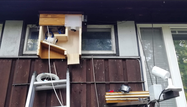
The topload is now changed to a smaller one, like this (Image 1.)
Resonance frequency with this topload is about 400 kHz.
I made a voltage divider of two non-inductive resistors, 33 MΩ and 2 MΩ, and connected an oscilloscope between points A and B (=ground) (Image 3.) With such a voltage divider the voltage over R2 is input voltage divided by 17.5 so multiplying the measured voltage by 17.5 gives the real voltage.
Here are results of the first measurement (Image4.)
It is clearly visible that one single MOT is not capable of keeping the voltage up over the whole duty cycle. Zooming in to the highest point of the half-wave revealed, that when the tubes are switched on and the primary is drawing current from the MOT, the voltage in point A is decreasing and goes as low as 700 V.
I then installed a diode and a capacitor as shown in Image 3. The capacitor is a 0.8 µF MO-capacitor. The diode is 11 pieces of 1N5408 (100V/3A) connected in series, image 5.
The idea with the capacitor was to smooth the voltage in the input at the tank circuit. The capacitor Cx should draw current from the MOT also when tubes are switched off and it should provide current in parallel with the MOT when tubes are switched on. This should provide more power to the primary circuit. The diode works as a half-wave rectifier because a VTTC doesn’t need the negative part of the half-wave so it is probably better to remove in this configuration.
According to the measurement, this is also what happened, Image 8 and 10.
The six configuration tested here:
The results are here.
All measurements in a table.
As seen in the table, adding Cx and Dx to the system has a remarkable influence on the spark length. Best cases to compare are those with one MOT (configuration 1 and 4) and those with MOT's (configuration 2 and 6). It's is clearly visible in this video too.
In both configurations 4 and 6 the MOT's are really working beyond their limits and are getting very hot very fast. These configurations would really need a staccato controller.
Because the voltage in configuration 4. and 6. is still lower than the peak voltage in configuration 1. and 2. the system would most likely benefit from even a stronger transformer or from more MOT's added in parallel with the two used here. Or from a bigger capacitor Cx and a staccato-controller. The idea here would be to charge the capacitor to full voltage and then burst the whole load into the system.
This VTTC was earlier tested with a voltage doubler made of the same diode and capacitor used here, but that did not produce the expected results. No significant change in the spark length.
Removing the diode and using only the capacitor produced somewhat weird results. Here are the scope image and a video with two MOT’s in parallel and the capacitor but no diode.
The VTTC was operated directly from mains (230V/50Hz) during these tests. No variac was used.
VTTC used here is based on the schema from Steve Wards except that instead of 811A the tubes are 572B, a matched pair. Images of the configuration can be seen in previous posts:
https://teslamuuntaja.blogspot.com/2020/04/vttc-1-osien-sijottelua.html
https://teslamuuntaja.blogspot.com/2020/04/vttc-1-ensio-ja-toisiokaamit.html
The topload is now changed to a smaller one, like this (Image 1.)
 |
| Image 1. |
Resonance frequency with this topload is about 400 kHz.
I made a voltage divider of two non-inductive resistors, 33 MΩ and 2 MΩ, and connected an oscilloscope between points A and B (=ground) (Image 3.) With such a voltage divider the voltage over R2 is input voltage divided by 17.5 so multiplying the measured voltage by 17.5 gives the real voltage.
 |
| Image 2. |
 |
| Image 3. |
Here are results of the first measurement (Image4.)
 |
| Image 4. Configuration 1. |
It is clearly visible that one single MOT is not capable of keeping the voltage up over the whole duty cycle. Zooming in to the highest point of the half-wave revealed, that when the tubes are switched on and the primary is drawing current from the MOT, the voltage in point A is decreasing and goes as low as 700 V.
I then installed a diode and a capacitor as shown in Image 3. The capacitor is a 0.8 µF MO-capacitor. The diode is 11 pieces of 1N5408 (100V/3A) connected in series, image 5.
 |
| Image 5. |
The idea with the capacitor was to smooth the voltage in the input at the tank circuit. The capacitor Cx should draw current from the MOT also when tubes are switched off and it should provide current in parallel with the MOT when tubes are switched on. This should provide more power to the primary circuit. The diode works as a half-wave rectifier because a VTTC doesn’t need the negative part of the half-wave so it is probably better to remove in this configuration.
According to the measurement, this is also what happened, Image 8 and 10.
The six configuration tested here:
- One MOT
- Two MOT's
- One MOT + diode
- One MOT + diode + capacitor
- Two MOT's + diode
- Two MOT's + diode + capacitor
The results are here.
 |
| Image 6. Configuration 2. |
 |
| Image 7. Configuration 3. |
 |
| Image 8. Configuration 4. |
 |
| Image 9. Configuration 5. |
 | |
|
V
min
|
V
max
|
V
diff
|
V
mean
|
Spark
lenght
cm
|
||
Conf. 1.
|
One MOT
|
700
|
3
570
|
2
870
|
2
135
|
18
|
Conf. 2.
|
Two MOT's
|
700
|
3 290
|
2 590
|
1 995
|
32
|
Conf. 3.
|
One MOT + diode
|
0
|
2 870
|
2 870
|
1 435
|
18
|
Conf. 4.
|
One MOT + diode + capacitor
|
840
|
1
540
|
700
|
1
190
|
28
|
Conf. 5.
|
Two MOT's + diode
|
140
|
2
590
|
2
450
|
1
365
|
31
|
Conf. 6.
|
Two MOT's + diode + capacitor
|
980
|
1
750
|
770
|
1
365
|
38
|
As seen in the table, adding Cx and Dx to the system has a remarkable influence on the spark length. Best cases to compare are those with one MOT (configuration 1 and 4) and those with MOT's (configuration 2 and 6). It's is clearly visible in this video too.
In both configurations 4 and 6 the MOT's are really working beyond their limits and are getting very hot very fast. These configurations would really need a staccato controller.
Because the voltage in configuration 4. and 6. is still lower than the peak voltage in configuration 1. and 2. the system would most likely benefit from even a stronger transformer or from more MOT's added in parallel with the two used here. Or from a bigger capacitor Cx and a staccato-controller. The idea here would be to charge the capacitor to full voltage and then burst the whole load into the system.
This VTTC was earlier tested with a voltage doubler made of the same diode and capacitor used here, but that did not produce the expected results. No significant change in the spark length.
Removing the diode and using only the capacitor produced somewhat weird results. Here are the scope image and a video with two MOT’s in parallel and the capacitor but no diode.
 |
| Image 12. |
The VTTC was operated directly from mains (230V/50Hz) during these tests. No variac was used.


Kommentit
Lähetä kommentti