Vacuum Tube Tesla Coil Staccato Controller with Arduino
I built a staccato controller for a vacuum tube Tesla coil using a microcontroller. I used an Arduino Nano, which is an older (2008) and well-known microcontroller based on the Atmega328. It's relatively slow compared to many newer microcontrollers, but still fast enough to follow the 50-hertz frequency of the mains power, which is the basis of the staccato controller's operation.
In the circuit diagram, at the bottom right, there is a transformer, 230/12 V 6 VA. I initially used a 2 VA printed circuit board transformer, but it had a tendency to overheat. A 4 VA transformer would likely be fine, but I installed a 6 VA transformer.
Above the transformer, there is a full-wave rectifier, BR1. Following the bridge is an electrolytic capacitor C1, rated at 1000 uF and 35 V. After that, there is a 7812 voltage regulator that steps the voltage down to 12 volts, which is the highest allowed operating voltage for the Nano. Even though the rated voltage of the transformer is 12 volts, it provides well over 12 volts when lightly loaded and rectified, which might exceed the Arduino's limits. The Arduino itself contains a regulator that further steps the voltage down to 5 volts.
Between the transformer and the rectifier bridge, a half-wave rectified current is taken via a diode to a voltage divider, consisting of two 1 kΩ resistors, R7 and R8. After the voltage divider, there is a 100 nF capacitor for filtering, followed by a 4.7-volt Zener diode to limit the voltage to Arduino's maximum of 5 volts. The resulting half-wave rectified and 4.7-volt limited voltage is fed into Arduino's analog input A1. Using this signal, Arduino controls the triac in the top left corner, which is triggered from Arduino's output D12 through a 220 Ω resistor.
The diagram can be found also here.
As a triac you can use at least types BT139-600E and T1610H, which are logic-level triacs and works well in this application. There is no optocoupler between the Arduino and the triac.
Below the Arduino, in the middle, are three 10 kΩ potentiometers to control the operation of the device. They are connected to Arduino analog inputs A2, A3, and A4. Above left is a pushbutton connected to 10 kΩ pull-down resistor R6 and Arduino digital input D2.
The components are assembled on a Velleman ECS3 prototyping circuit board with three-hole copper strips. It has proved handy in many projects.
The assembly drawings have been designed using LibreCAD. The components are drawn in red lines. Jumper wires above the circuit board are drawn in green. Those below are drawn in blue and those need to be isolated. External component connection wires are drawn in green, yellow, and blue lines. It's not recommended to solder the Arduino Nano directly onto the circuit board. Instead, it should be mounted on pin headers so that it can be easily detached when needed. To install the pin headers correctly, it's recommended to press the Nano onto the headers before soldering. This way, the headers will align in the right position.
The CAD images above can be found here.
For external components, the board is fitted with pin terminals to which the wires can be connected.
The circuit board is made to fit into the GAINTA G 212C enclosure. It case has a transparent cover because it is nice to see what is inside the device. The potentiometers are mounted on one long side of the case, the push button on the lid, the mains lead connector on the other long side as well as two banana plugs for the triac input.
The Nano monitors the phase of the half-wave rectified voltage applied to pin A1 and detects the points where the waveform starts to rise. At that moment, the triac is triggered to conduct with a 1 ms pulse. Potentiometer R4 is used to adjust how often the triac is triggered. When the potentiometer is turned towards one end, the triac is triggered on every half-wave. Near the other end, it's triggered every 50 half-waves, which corresponds to once per second on a 50 Hz power grid.
When the potentiometer is turned all the way to the opposite end, the triac is no longer triggered at all. These values can be customized in the program code if desired.
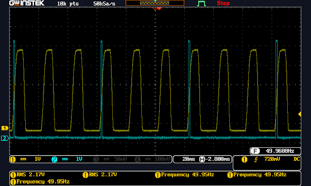
In the oscilloscope image, you can see the half-waves of the mains current in yellow and the triggering pulses of the triac in blue.
 |
| Triggering every second half wave. |
 |
| Two in a row. |
 |
| Three in a row. |
 |
| Four in a row. |
Potentiometer R2 is used to adjust the timing of the trigger. This allows for adjusting the intensity of the spark discharge. The most intense discharge occurs when the trigger is given right at the beginning of the half-wave. By adjusting the potentiometer, the trigger timing can be delayed. The oscilloscope provides a clear visual demonstration of how this adjustment works.
The above pictures were taken when the VTTC was not in use. It causes interference with nearby circuits when running and the oscilloscope image looks like this when the VTTC is in use.
However, the Staccato controller still operates without disturbance. Capacitor C2 was added to the circuit to eliminate some issues caused by interference.
By using the push button, a single trigger can be given. If potentiometer R2 is adjusted to a point where the device does not provide pulses, the push button can be used to give one pulse at a time. The length and intensity of the pulse are determined by the positions of potentiometers R2 and R3. The device stops giving pulses when the button is pressed, so it can also be used to interrupt the operation of the device.
LED D3 flashes in sync with the triac trigger pulses.
For the staccato controller to work, it's crucial that both the staccato controller and the VTTC are connected to the same phase and at the same phase angle. If the device doesn't start working, try reversing either the plug of the VTTC or the staccato controller's power cord.
Arduino can be programmed to do almost anything. This includes generating different rhythms at varying intensities, among many other functionalities. In the video, a couple of examples are demonstrated.
The device has been tested with a dual 811A VTTC.
It has not been tested on a 60 Hz grid, but it should work fine. In a 120-volt grid, the transformer must, of course, be rated at 120/12 V.
While there are good and functional staccato controller designs available, such as this one and this one, or one that can be purchased as a kit, I think a controller made with Arduino is significantly simpler to build and more versatile. This is because it can be programmed to function in various ways.
You can purchase Arduino Nano clones for just a few dollars, for example on AliExpress. Most likely, other microcontrollers would work as well in this application. However, it's important to remember that in many microcontrollers the logic voltage is 3.3 volts, which means that component values must be adjusted accordingly.
Watch the video to see how this works.
I hope this presentation was helpful. If you have any ideas or comments or decide to build your own controller following these instructions, please let me know in the comments. You are free to use the provided Arduino code, modify it, or create your own from scratch.


Cannot compile Code , error message:
VastaaPoistaC:\Users\SERVIS~1\AppData\Local\Temp\arduino_modified_sketch_923106\sketch_jan03a.ino: In function 'void fire()':
sketch_jan03a:43:21: error: expected ';' before numeric constant
for (int ii=0; ii 15){}
^~
C:\Users\SERVIS~1\AppData\Local\Temp\arduino_modified_sketch_923106\sketch_jan03a.ino: At global scope:
sketch_jan03a:48:3: error: expected declaration before '}' token
}
^
exit status 1
expected ';' before numeric constant
Please if I can get the complete code (with potLenght and potDelay). Thank you
PoistaHi! Sorry for the delay. I'll check that as soon as I have the time, maybe even tonight. There's probably some small mistake in the code when I copied it here to the blog.
PoistaIt looks like Blogger had messed up the code. Now it's fixed. Thank you for noticing!
Poista